How do I find the right filter for my particular application and what is the difference between them? (Part 2)
Short pass filters
Short pass filters have almost the same characteristics as the long pass filters I presented to you in Spectrum no. 15. The difference is that they are transparent at shorter wavelengths.
Common characteristics of both short and long pass filters are the 5% and 50% cut-off wavelengths and the cut-on slope.
When compared to cars, you can say that long pass filters drive forward while short pass filters all drive backwards. Also, from a technical point of view, short pass filters start in the lower middle range.
The most basic models are dielectric short pass filters of the XXXFL series. The higher middle class models can be found in the DYYYSP series, while the HQYYYSP and ETYYYSP series constitute the luxury class.
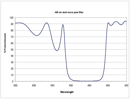
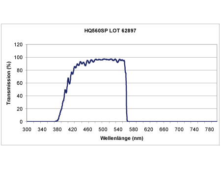
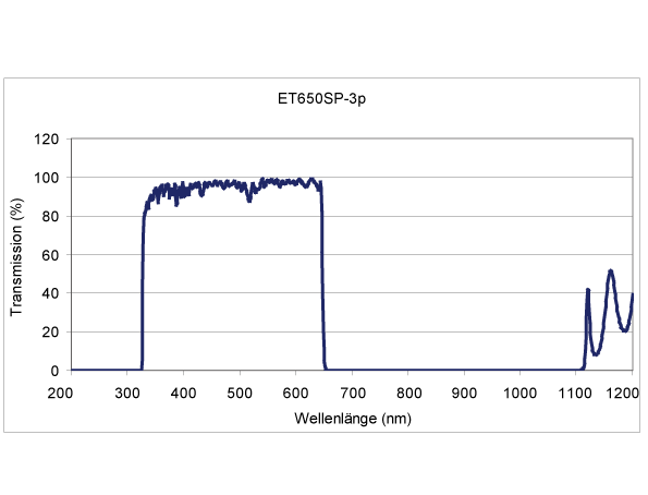
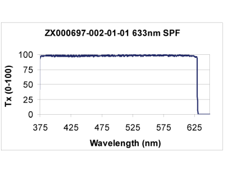
Just like with long pass filters, the edge width (or the time they take from 0 - 100 km/h) determines the filter category. Figures 1 - 4 show typical examples.
However, there is one major difference between these two edge filter types: long pass filters are fully blocked for wavelengths below the edge wavelength. Short pass filters are almost always only blocked to 1.33 times the edge wavelength for wavelengths above the cut-off wavelength. This means, the filters transmit at wavelengths larger 1.33 times the cut-off.
To avoid this, the filters need to be refined – just like cars. Refinement is complex, costly and requires a great deal of technical skill. This is greatly illustrated in figure 1, which shows a 400 nm short pass filter type 400FL07.
Band pass filters
As the name suggests, this filter type transmits an entire spectral band. To be able to describe them better, I would like to first explain a few technical terms that are frequently used for their characterization.
To determine the central wavelength (CWL), it is necessary to identify the filter’s maximum transmission. A horizontal line (parallel to the x-axis) is drawn at Tx (max.)/2 which crosses the filter’s transmission curve at two points. The resulting width is called full width (at) half maximum (FWHM). Draw a vertical line (parallel to the y-axis) that cuts the FWHM in half to get the CWL. Note that the peak wavelength Tx (pk) of a band pass filter is not necessarily identical with the CWL.
Again, the cut-on and cut-off slope of the band pass filter are important parameters. This is why for very wide band passes, the 5% and 50% cut-on and cut-off wavelengths are always indicated. For middle-sized or small band filters, the 1% and 5% wavelengths (absolute transmission value) and the FWHM are indicated.
While the low-slung hot rods in the streets are considered the more valuable and cool the larger their tires and track widths, filters are the exact opposite: the smaller and steeper their curve (at best like a rectangular column), the more valuable and suitable they are. Well, it is known that the low-slung cars are no good in traffic calmed areas (the little bumps are considered their natural enemies). This is why “low-slung, large-tire” filters with large 1% and 5% widths are only suitable for standard applications without any close-by obstacles.
For sophisticated applications where the obstacle is close at hand (for example fluorescence or Raman spectroscopy), filters with small and rectangular curves are needed.
This filter series will be continued in one of our next Spectrum editions (Author of this article is Jürgen Fischbach, OAP now).


