The ideal tool for measuring the quantum Hall effect
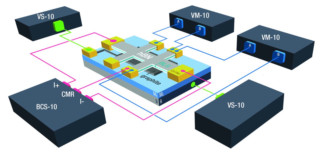
Fig. 1: M81 circuit diagram for a multi-gate reverb bar device
The study of quantum transport in nanomaterials, such as bilayer graphene, has become a large and exciting field due to the unique properties that can be observed. Examples are (unexpected) transitions like superconductivity, magnetic ordering, charge density waves, and other correlated phenomena. By changing experimental variables like temperature, field-effect gates, or magnetic fields, the properties and behaviors of the sample can be tuned. These nanomaterial samples can be analyzed and characterized by electrical transport techniques, such as the classical Hall effect (HE) and the quantum Hall effect (QHE).
Within the family of two-dimensional electron gas (2DEG) systems, nanomaterials allow for the observation of the QHE. The QHE gives an insight into the energy states, degeneracies and the band structure of the sample. Materials that belong ot the 2DEG family are graphene or boundary layers between semiconductors like GaAs/AlGaAs structures.
When measuring Hall resistance (Hall voltage divided by current), Hall 2DEG materials exhibit plateaus of about 25.8 kΩ and corresponding integer fractions. This value is known as Von-Klitzing constant RK and can be attributed to h/e2. This is the result of the quantization of electron energy level.
The experiment requires the presence of a magnetic field, low temperatures and sensitive yet flexible measurement electronics. This article features the setup of such an experiment.
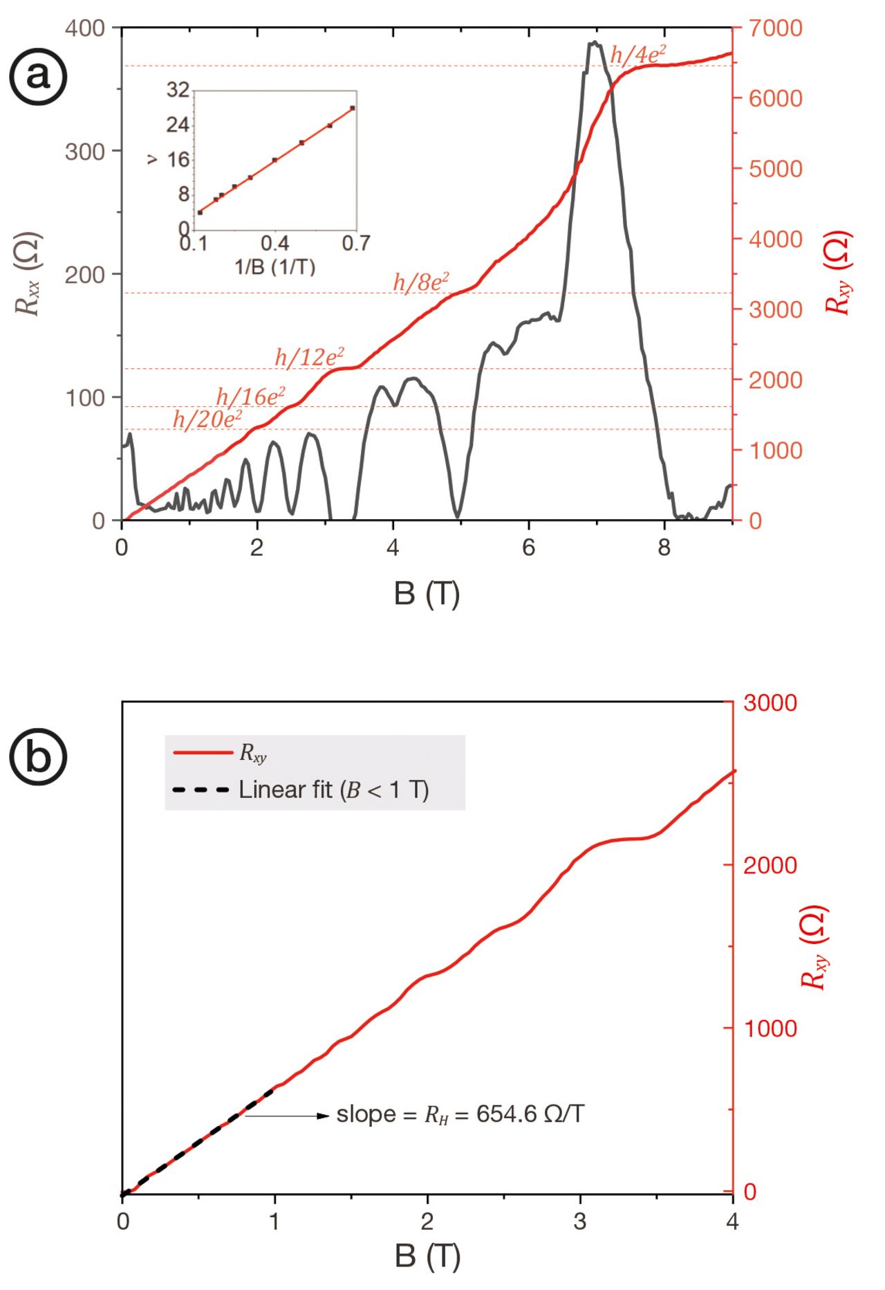
Fig. 2: (a) σxx and σxy as a function of carrier density after gate to carrier density conversion, highlighting steps of 4e2/h for B = 2 T; (b) σxy versus carrier density density for 2 T and 6 T, highlighting steps of e2/h for B = 6 T.
Fig. 1 shows a schematic layout. The sample is bilayer graphene (BLG) which is encapsulated with boron nitride (hbn). The probe has a Hall bar structure type 1-2-2-1. On the bottom (see “graphite”) there is an additional contact for gate voltage.
Measurement electronics include two voltage sources (VS-10), one current source (BCS-10) and two voltmeters (VM-10). The balanced current source provides an AC current of 50 nA at 17 Hz. The two voltmeters VM-10 measure the longitudinal Vxx and the transversal component Vxy of the Hall voltage. The two VS-10 voltage sources provide gate voltage for tuning carrier density and contact resistance. The measured voltages enable the calculation of the corresponding longitudinal and transversal Hall resistances Rxx und Rxy.
Fig. 2 shows Rxx und Rxy as functions of the magnetic field. It also shows typical quantum oscillations and quantization plateaus.
About the experiment M81-SSM modules were used for the electrical setup. The M81 offers high flexibility when it comes to source and measuring modules. A total of 6 modules can be combined on an M81 main board. The above application requires low noise and high sensitivity both of which are also ensured by the M81 setup.
The DryMag from Lake Shore was used as crystat. DryMag features a base temperature of 1.5 K and a superconducting 9 T magnet.
This article is based on an application note from Lake Shore. The app note describes the setup in more details and depicts further contextual information like the influence of gate voltage, Landau fans, meausrement of Hall parameters, and more.
You can get a full copy of the app note “Quantum Hall Effect Measurements in Nanomaterials“ off the Lake Shore website or through us.
We look forward to your comments!