How do I find the right filter for my particular application and what is the difference between them? (part 3)
Bandpass filters
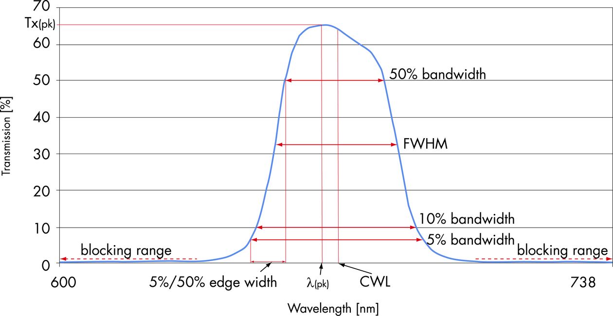
The main parameters that characterize a bandpass filter were described in part 2 of this article. Here is a short summary:
- CWL: Central wavelength
- FWHM: Full width at half maximum; the spectral bandwidth of the filter at half the maximum transmission
- Tx(pk): Maximum transmission
- λ(pk: ) Wavelength at which maximum transmission is reached
- X%-BW: X% bandwidth
- BW 0.1%; 1%; 5%: Bandwidth a filter has at 0.1%; 1%; or 5% absolute transmission
Cut-on/cut-off slope
Do you remember? How much time does a filter need to get from 0 to 100 km/h (that is from 0 to full transmission) and vice versa? The terms cut-on and cut-off edge width are used to describe this value in nanometers. They indicate the width (in nm) the filter “needs” from, for example, 0.1% to maximum transmission and vice versa. Fig. 1 shows a summary and image of all relevant filter characteristics.
Like the word suggests, a bandpass filter is supposed to only transmit a certain spectral band. All other light is supposed to be blocked. It is important to know the area that is to be blocked and the intensity of the blocking.
We know from cars that as drivers, we want noise to be suppressed as much as possible, so we can enjoy our music or have a chat with our fellow travelers. Now, low-budget cars of a simpler standard usually don’t need a speedometer - at around 40 km/h the left half of the dashboard starts rattling, at 60 km/h the interior lining of the right door joins in, at 80 km/h you can hear the engine sing, and from 120 km/h you can forget about the discussion you were just having with your neighbor. According to national law, you are now legally required to wear ear muffs. Luxury cars, on the other hand, will never be louder than a light breeze. Neither rattling nor other noises will interfere with the Hi-Fi sound of Beethoven’s Fifth. When categorizing filters, thin color glass filters and filters with single or only a few layers are considered simple standard and “loud”. Typically they feature OD2 or OD3 blocking. “OD2 blocking” means there is a remaining transmission of 1%. OD4 means a remaining transmission of 0.01% and OD6, which would be the luxury car in our example, has a remaining transmission of 0.0001%. Here is to the mathematicians among you:
Tx(%)=100 x 10exp.-OD.
Our classic standard filters of the XXXFSYY series belong to the middle class. Transmission is not extremely high, but they have OD4 blocking for the full range from deep UV to far IR, meaning, their remaining transmission is 0.01% max. This is important when the sensors or detectors used (photomultipliers, thermo elements, etc.) are also sensitive in the NIR (0.7 - 2 μm) or MIR (2.1 - approx. 15 μm). Since Si-based detectors or sensors (which are “blind” for wavelengths larger 1100 nm) are used for a great number of applications, blocking to this wavelength is usually sufficient.
We now offer a new filter series of reduced blocking: AAAFSXBB. These are highly transmissive filters (Tx>80%) blocked to 800 nm, 1000 nm, or 1200 nm, depending on their CWL.
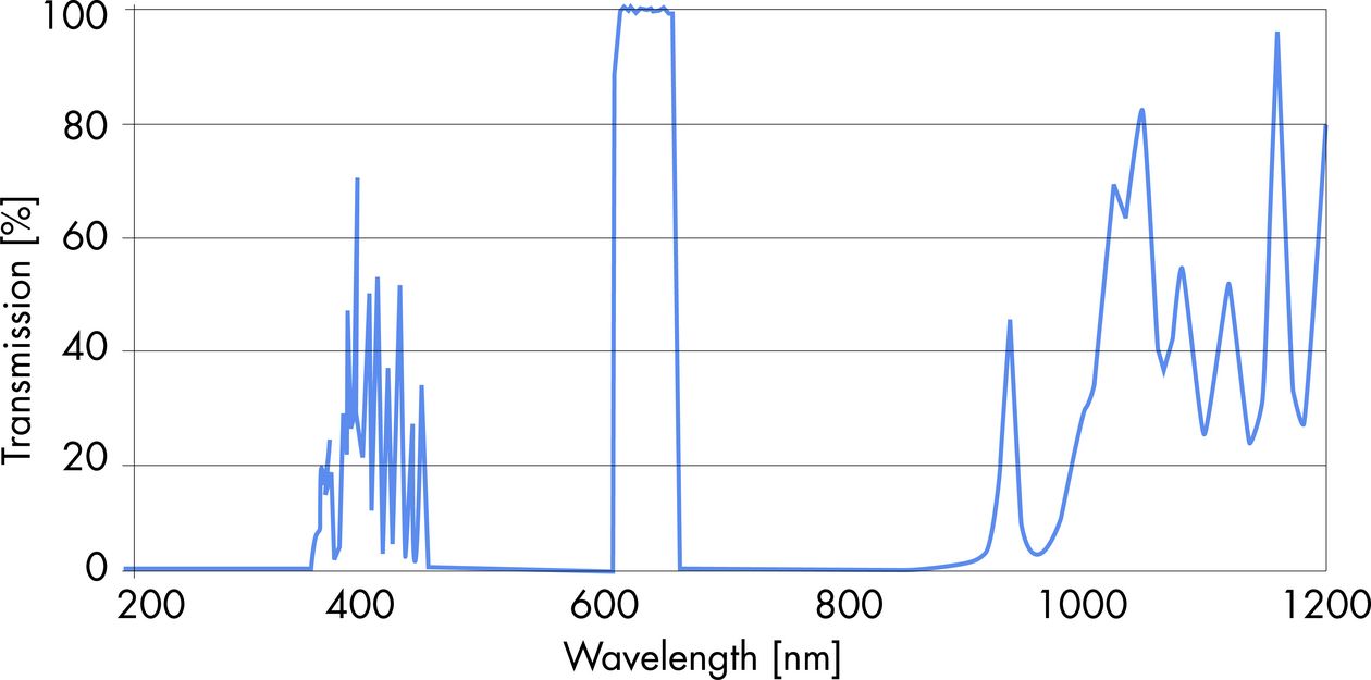
Please be careful when choosing the right filter: in fluorescence analysis, for example, the required excitation and emission filters are chosen according to the dye. But even though these filters are blocked high (OD5 to > OD6), they are blocked only for a limited area. See figure 2 for illustration.
Just like cars come in a variety of models and colors with little or lots of horse power, standard filters are also available in many different versions. Some of them I would like to present to you in more detail. Let me begin with the low-budget class.
Filters of the XXXFSYY series come in 10 nm steps for CWLs of 195 - 1100 nm. The standard FWHM is 10 nm. We offer filters with narrower bands for analysis and laser lines and models with 20, 40, and 80 - 100 nm bandwidths in 50 nm steps. They come in three standard sizes with diameters of 12.5, 25 and 50 mm.
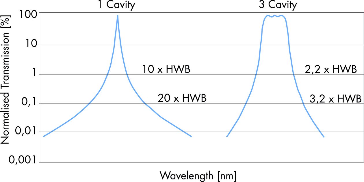
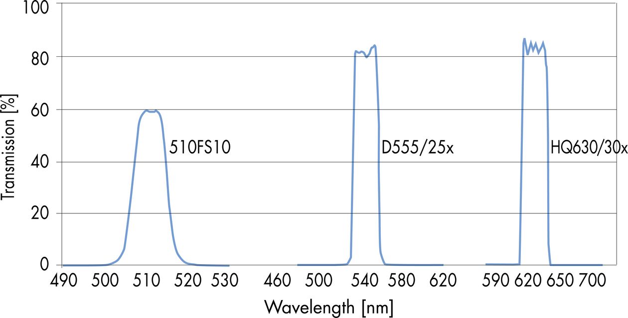
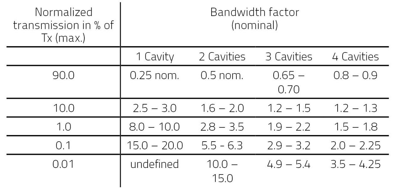
The transmission characteristic of these filters is Gaussian or bell-shaped, the width of the basis depends on the number of cavities. The 0.01%, 1% and 10% bandwidths are pretty wide compared to the filters of the middle and upper class I will describe later. The table gives an overview of typical values. Fig. 3 depicts a 1-cavity and 3-cavity filter, respectively. Upper middle class filters have a more or less standardized design. Normally, they consist of two components with soft coatings on the inside. For better protection, they are mounted in an aluminum ring. Typically, they have 80% transmission (depending on the CWL) and OD5 blocking or higher. These are the precursors of the hard-coated top-of-the-range models. The cut-on and cut-off bandwidth from Tx (5%) to Tx (50%) lie between 1.5 nm and 2.0 nm for models type D, between 1.3 and 1.6 nm for models type HQ, and between 1.2 - 1.4 nm for models type HHQ (fig. 4). Due to their multi-component design, filters of this and the FS series cannot be mechanically manipulated (for example cut) after coating. Filters of the luxury class (those that let you listen to the finest classical tune while driving) are state-of-the-art, hard-coated, single-component filters of the ET (extended transmission) and HT (high transmission) series. They usually feature everything you could possibly ask of a filter:
- 5%- and 50% cut-on and cut-off bandwidth of approx. 1 nm
- Transmissions way larger 90% up to 98%
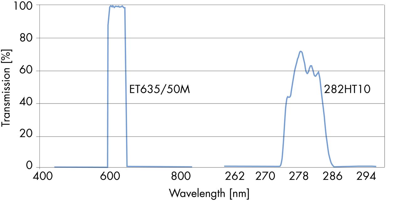
Blocking from 300 nm to at least 800 nm, sometimes even to 1200 nm - OD6 blockings and better are possible. Latest developments have provided UV filters to 220 nm with FWHMs of 5, 10 and 20 nm with OD4 blockings to 800 nm and OD2 blockings to 1100 nm, while at the same time reaching transmissions of 65% to 80%. This type of filter is almost indestructible. And since they usually consist of one 1 - 2 mm thick component, they may well be mechanically finished after coating. We have tested a 282 nm filter with 10 nm bandwidth, 71% transmission without any additional cooling in front of a 1 kW Xenon light source – it was a raving success! Figure 5 shows typical transmission curves of these miracle filters.


