

Fibre-Coupled Optical Homogeniser for Large-Area Uniform Illumination – Bentham FCH
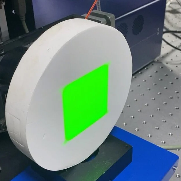
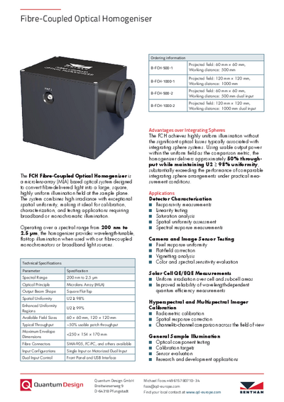
From BenthamThe Bentham FCH Fibre-Coupled Optical Homogeniser converts fibre-delivered broadband or monochromatic light into a large, square, spatially uniform illumination field. Based on a microlens-array optical design, it supports detector and image-sensor characterisation, QE/EQE measurements, hyperspectral and multispectral imager calibration, and general sample illumination. Two field sizes and single- or dual-input configurations allow flexible integration into modular optical spectroscopy setups.
- Spectral range from 200 nm to 2.5 µm
- Square flat-top illumination field
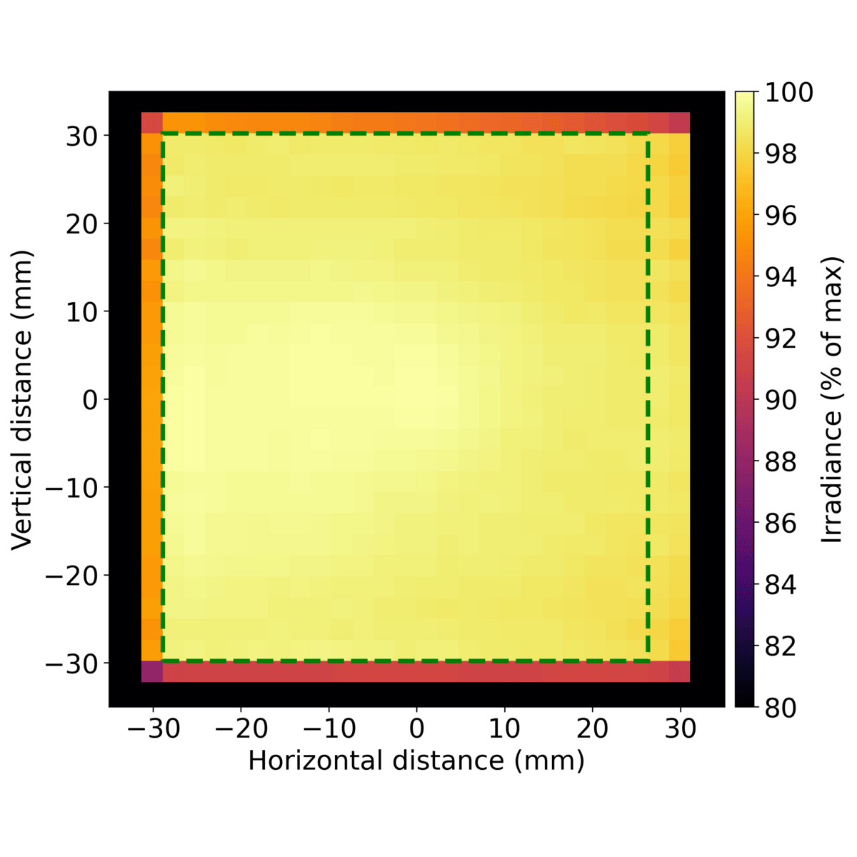
- Spatial uniformity U2 ≥ 98%
- Enhanced uniformity regions with U2 ≥ 99%
- 60 × 60 mm or 120 × 120 mm projected field
- Single passive or motorised dual fibre input
Further information
Why Spatially Uniform Illumination Matters
In detector, camera, sensor and sample measurements, variations in the illumination field can influence the measured response. If irradiance changes across the active area, the recorded signal may contain contributions from both the device under test and the illumination pattern.
The FCH reduces this influence by converting fibre-delivered light into a spatially uniform square field at a defined working plane. This is particularly relevant when detector or sample response needs to be separated from spatial variations in the illumination.
Typical applications include detector characterisation, camera flat-field measurements, QE/EQE measurements and calibration setups for hyperspectral and multispectral imagers.
How the FCH Generates a Uniform Field
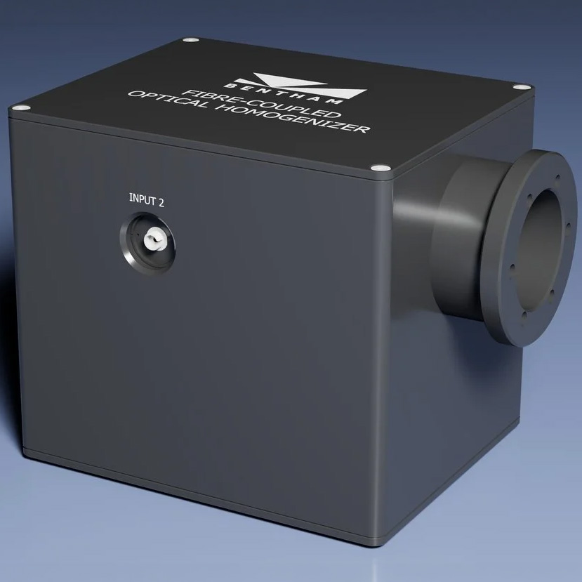
The optical system combines a fibre input, a collimating lens, a bespoke pair of microlens arrays and a custom three-element Fourier lens.
The fibre output is first collimated before entering the microlens-array stage. The MLA pair redistributes the incident light, while the Fourier lens projects the homogenised field onto the working plane.
Fibre Input → Collimation → Microlens Array Pair → Fourier Lens → Uniform Working Plane
Bentham specifies the optical design for a spectral range from 200 nm to 2.5 µm. The three-element Fourier lens is designed to control chromatic aberration across this range.
Large-Area Illumination at a Defined Working Plane
Two standard output geometries are available:
- FCH-500: 60 × 60 mm projected field at a nominal working distance of 500 mm
- FCH-1000: 120 × 120 mm projected field at a nominal working distance of 1000 mm
The specified field geometry and spatial uniformity relate to the defined working plane. Correct positioning of the detector, sensor, sample or calibration target is therefore an important part of the experimental setup.
Spatial uniformity is specified as U2 ≥ 98%, with enhanced uniformity regions reaching U2 ≥ 99%.
High Usable Optical Throughput
Uniform illumination is most useful when sufficient optical power reaches the measurement area.
Bentham specifies a typical usable-patch throughput of approximately 50% at 550 nm. This value refers to the optical power delivered into the useful uniform field and should not be interpreted as constant transmission across the complete 200 nm to 2.5 µm spectral range.
Bentham positions the FCH as an alternative to integrating-sphere arrangements for applications where spatial uniformity and usable irradiance at a practical working distance are both important. The comparison depends on field geometry, working distance and the definition of the useful uniform area.
Integration Into Modular Optical Spectroscopy Setups
The fibre-coupled architecture allows the FCH to be combined with different light sources and spectral-selection systems.
A typical setup can be represented as:
Light Source → Monochromator or Tuneable Source → Multimode Fibre → FCH → Detector, Sensor or Sample
For measurements using a suitable fibre-coupled LED, laser or broadband source, a separate spectral-selection stage may not be required.
The FCH is designed for 0.22 NA multimode fibre, typically with a fibre-core diameter between 200 and 800 µm. SMA-905, FC-PC and other connector options are available.
Single or Dual Fibre Input
Both field-size variants are available with either a single passive input or a motorised dual-input configuration.
The single-input configuration is suited to setups using one permanently connected fibre-coupled source and does not require powered switching.
The dual-input configuration allows two sources to remain connected. Source selection can be controlled from the front panel or via USB. This is useful when a setup needs to alternate between complementary sources or spectral ranges without reconnecting the fibre path.
Models
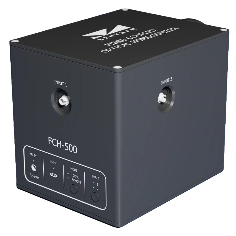
The FCH-500 provides a 60 × 60 mm square projected field at a nominal working distance of 500 mm.
Available configurations:
B-FCH-500-1
Single passive fibre input
B-FCH-500-2
Motorised dual fibre input
The FCH-1000 provides a 120 × 120 mm square projected field at a nominal working distance of 1000 mm.
Available configurations:
B-FCH-1000-1
Single passive fibre input
B-FCH-1000-2
Motorised dual fibre input
Specifications
| Parameter | Specification |
| Spectral Range | 200 nm to 2.5 µm |
| Optical Principle | Microlens Array (MLA) |
| Output Beam Shape | Square flat-top |
| Spatial Uniformity | U2 ≥ 98% |
| Enhanced Uniformity Regions | U2 ≥ 99% |
| Available Field Sizes | 60 × 60 mm / 120 × 120 mm |
| Nominal Working Distance | 500 mm / 1000 mm |
| Typical Throughput | Approx. 50% usable patch throughput at 550 nm |
| Fibre Type | Multimode fibre |
| Designed Fibre NA | 0.22 NA |
| Recommended Fibre Core | 200–800 µm |
| Fibre Connectors | SMA-905, FC-PC, others available |
| Input Configurations | Single input / motorised dual input |
| Dual-Input Control | Front panel and USB interface |
| Maximum Envelope Dimensions | <250 × 154 × 170 mm |
The throughput value is stated for 550 nm and is not a wavelength-independent specification.
Applications
Detector Characterisation
Spatial variations in illumination can make detector measurements difficult to interpret because changes in the recorded signal may originate from either the detector or the illumination field.
The FCH supports measurements such as:
- Responsivity
- Linearity
- Saturation
- Spatial uniformity
- Spectral response
A uniform input field helps compare different detector regions or elements under equivalent illumination conditions.
Camera and Image Sensor Testing
Uniform illumination is important when evaluating spatial variations across camera and image-sensor arrays.
Typical applications include:
- Pixel response uniformity
- Flat-field correction
- Vignetting analysis
- Colour and spectral sensitivity evaluation
A defined illumination field helps reduce the contribution of source gradients when evaluating pixel-to-pixel or field-dependent response.
Solar Cell QE/EQE Measurements
For wavelength-dependent quantum-efficiency measurements, different areas of a solar cell or sub-cell should receive comparable irradiation.
Combined with a suitable monochromatic or tuneable fibre-coupled source, the FCH can support:
- Spectral-response measurements
- Quantum-efficiency measurements
- EQE measurements
The FCH provides the illumination stage within the setup and is not itself a complete QE/EQE measurement system.
Hyperspectral and Multispectral Imager Calibration
Hyperspectral and multispectral imagers combine spatial and spectral information. Non-uniform illumination can therefore affect both spatial-response measurements and comparisons between spectral channels.
The FCH supports applications including:
- Radiometric calibration setups
- Spatial-response correction
- Channel-to-channel comparison
- Remote-sensing sensor evaluation
The homogeniser provides the illumination field. Traceable radiometric calibration still depends on the calibrated sources, detectors and reference standards used in the complete system.
General Sample Illumination
The FCH can also be used wherever a defined uniform illumination field is required for laboratory testing and research.
Typical applications include:
- Optical component testing
- Calibration targets
- Sensor evaluation
- Material and sample illumination
- Research and development setups
Downloads
Contact

Navigation
Categories
Contact
Quantum Design SA
Rue du Nord3
CH-1400 Yverdon-les-Bains
Switzerland
| Phone: | +41 21 8699-033 |
| E-Mail: | suisse@qd-europe.com |
Support