Attenuated Total Reflexion ATR – fundamentals, band distortion and band shift
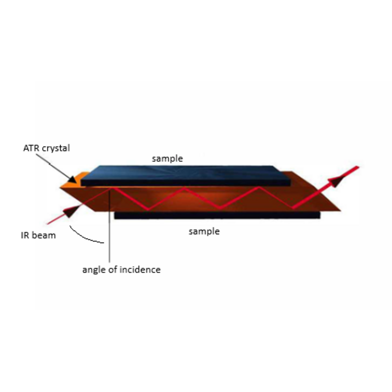
Internal reflection occurs when infrared radiation enters an ATR crystal made of a highly refractive infrared transmitting material. The crystal is designed to enable internal reflection, creating an evanescent wave at the crystal surface. This wave extends into a sample that is held in intimate contact with the crystal material and so absorption spectra can be recorded as a result.
One of the major advantages of ATR spectroscopy lies in that sample preparation becomes easier, and the need for complex sample preparation is often avoided completely. High mechanical stability and outstanding chemical resistance have made diamond ATR a highly versatile method for routine analysis of solid and liquid samples in many laboratories.
- Minimal to no sample preparation, allowing analysis of samples in their natural form.
- Thick or strongly absorbing samples measurable.
- Very thin samples measurable, since no disturbance due to interference
- Surface sensitive. For materials consisting of several layers, only the top layer is detected.
- Sample is in direct contact with ATR crystal, thus contamination by previous sample is possible.
- Not applicable for rough samples and very hard materials that cannot be brought into contact with the ATR crystal.
Further information
How Attenuated Total Reflexion works
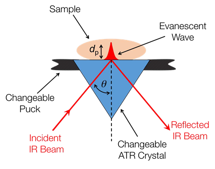
Figure 1: Graphical representation of a single bounce ATR.
Figure 1 demonstrates the principle behind the single bounce ATR, where IR light from a spectrometer is internally reflected in the ATR crystal and interacts with the sample at the crystal interface. Partial penetration of the IR light by an evanescent wave allows an absorption spectrum to be recorded.
The absorbance and depth of penetration (dp) of the evanescent wave depend on the following factors:
- the refractive index of the crystal, n1
- the refractive index of the sample, n2
- the angle of incidence, θ
- the wavelength of the light, λ

Table 1 shows the physical properties of different ATR crystals and the value of dp when n2 = 1.5, 0 - 45° and λ = 10 µm. The typical value of dp ranges from 2-4 µm depending on the crystal.
For example, a Ge crystal provides a shorter sample penetration depth than a ZnSe crystal, which is ideal for strongly absorbing samples. However, its effective IR absorption range is limited, whereas a range of 4000–400cm-1 can be achieved by using the extended mono-crystalline type IIIa diamond crystal.
| Crystal | n1 | dp µm | IR range / cm 1 | Uses |
| ZnSe | 2.4 | 2.01 | 7800 – | General |
| Diamond | 2.4 | 2.01 | 7800 – | Harder & chemically |
| Extended Diamond | 2.4 | 2.01 | 10000 – | Shorter freq. |
| Ge | 4.0 | 0.66 | 5500 – | Highly conc. samples |
Table 1: Physical properties of the ATR crystals.
Figure 2 shows that ZnSe and Diamond have similar refractive indices and hence have similar penetration depths, while Ge is significantly different, so provides a lower penetration depth.
Intensity of absorbance bands
At higher frequencies, the relative absorbance of a sample is lower in the spectrum recorded using the ATR. This is because the penetration depth of IR light into the sample depends on the refractive index of the crystal, which changes as a function of frequency.
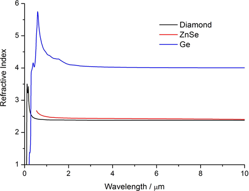
Figure 2: The refractive index of Ge, ZnSe and Diamond.
Figure 3 shows in more detail how the refractive index of ZnSe changes with wavelength at standard room temperature and pressure.
Consequently, the depth of penetration changes with the refractive index and hence the amount of light absorbed by the sample.
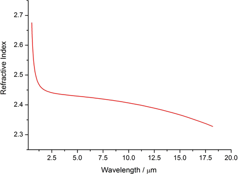
Figure 3: The refractive index of ZnSe
Summary of basics
The depth of penetration of the evanescent wave into the sample is a function of the crystal material and the angle of incidence for the infrared beam traversing through the crystal to the sample surface interface. Deeper penetration into a sample is achieved with either a smaller incident angle or a lower refractive index ATR crystal. In general the depth of penetration into a sample increases with increasing wavelength of light.
Spectral effects in ATR and differences to transmissions spectra
When obtaining an Infrared spectrum via ATR spectroscopy, the spectrum will be different to that obtained for the same sample when collected as a transmission spectrum. The differences can be accounted for by the fundamental way the sample information is being collected. Principally, transmission spectroscopy is the passage of light through an entire sample, whereas ATR spectroscopy is the interaction of light by passage into the surface of a sample species. Note that neither method can be regarded as giving the “correct” spectrum – they are simply different. However, as many spectral libraries are made using transmission measurements it can sometimes be useful to understand the differences.
Any differences in the spectra may be described as wavelength dependence, band distortion and band shift and can be explained thus.
Wavelength Dependence
In a transmission measurement of a sample, all wavelengths traverse the same total physical thickness of the sample material. However, in an ATR measurement the penetration depth of the light is a function of both the wavelength and the refractive index difference between the sample and the ATR crystal. The result of this is that the band intensities at different wavelengths will differ between a transmission measurement and an ATR measurement of the same material. The penetration depth (and therefore the apparent absorption intensity of the material) increases linearly with wavelength – bands at long wavelengths appear relatively stronger than bands at short wavelengths. This effect can be corrected mathematically to give a more “transmission- like” spectrum if desired, and most instrument software packages include some form of “ATR correction” algorithm to do this. Note that these algorithms cannot allow for any change of sample refractive index with wavelength – but as this is normally fairly small it is usually ignored.
Band Shifts
Band shifts (movement of the peak wavenumber position) will occur for two main reasons.
- Broad bands can be slightly shifted to longer wavelengths due to the wavelength dependent penetration depth change across the band (as described above). This will be corrected with the same ATR correction algorithm that is used to give more “transmission-like” band intensities.
- In many materials the refractive index can change significantly across an absorption band. This causes a variation in the penetration depth across the band and will “skew” it to longer wavelengths compared to the transmission spectrum band positions. The amount of shift will depend on the refractive index change across the band and this will be different for different bands in the spectrum. In practice, these shifts are not usually sufficient to cause any problem in library searching.
Band Distortion
Sometimes in ATR measurements the absorption bands can become slightly asymmetric compared to the bands seen in transmission measurements. The changes seen in the band shape arise because of the rapid change of refractive index of the sample across the bands. The refractive index of the sample varies from a low value on the short wavelength side of the band to a high value on the long wavelength side. This causes the effective penetration depth to also rapidly increase toward the long wavelength side and causes the characteristic shape of the bands seen. The effect is more pronounced if the ATR is working near to the critical angle (where the effective penetration depth goes to infinity).
To achieve the best sensitivity from any ATR it is important that it operates reasonably near to the critical angle. However, the critical angle varies depending on the refractive index of the sample and this means that high index materials (such as some polymers) end up working closer to the critical angle than the majority of samples that have a lower index. If the sample also has a significant variation of refractive index across its bands then distortion becomes very obvious.
There are several solutions to minimise the effect.
- The first is to ignore it (it is irrelevant for most quantitative analyses, as it is entirely reproducible between the calibration and sample data).
- The second is to use a higher refractive index ATR material.
With a Germanium crystal, the critical angle is much smaller so the effect is greatly reduced. However, the disadvantage is that the sensitivity of the ATR is also reduced.
- The third possibility is to mask off some of the rays in the ATR that are close to the critical angle. The energy loss is very small (because the rays close to critical angle were being strongly absorbed anyway) but the improvement in band shape is significant.
Conclusions
None of these observations are indicative of a "fault" in the technique or the accessory. All ATR measurements will show these effects but the band distortion effect can vary between different accessories. If an ATR system shows less band distortion then it will be operating further from the critical angle or with a higher refractive index crystal and will therefore be less sensitive.
Contact

Navigation
Categories
Contact
Quantum Design GmbH
Breitwieserweg 9
64319 Pfungstadt
Germany
| Phone: | +49 6157 80710-0 |
| E-mail: | germanyqd-europe.com |

