Short introduction: Ellipsometry
What is Ellipsometry?
This brief introduction to ellipsometry is targeted to the novice and provides a fundamental description of ellipsometry measurements and typical data analysis procedures. The primary applications of ellipsometry are also covered.
Further information
As light reflects or transmits from a material structure there is a change in polarization. Ellipsometry measures this response which depends on optical properties and thickness of individual materials. Ellipsometry is primarily used to determine optical constants and film thickness, but also to characterize composition, crystallinity, roughness, doping concentration, and other material properties associated with a change in optical response.
Applications areas are basic research in physical sciences, semiconductor and data storage solutions, flat panel displays, communication, biosensors, and optical coating industries. Ellipsometry also has the flexibility to measure most material types: dielectrics, semiconductors, metals, superconductors, organics, biological coatings and composites.
Polarized light definition
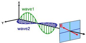
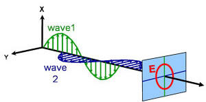
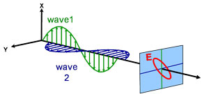
Light can be described as an electromagnetic wave traveling through space. The way an electromagnetic wave’s field behaves in relation to space and time is referred to as polarization. Light is considered to be unpolarized when its orientation and phase are totally arbitrary. Ellipsometry, however, measures polarized light – an electric field that follows a specific path and has a distinct shape at any given point. An electromagnetic wave which travels in z-direction can be described by its x- and y- components, because its electric field is always orthogonal to the propagation direction. When two orthogonal light waves are in phase, the resulting light is linearly polarized. Its orientation is determined by the relative amplitudes. The light is considered circularly polarized if the orthogonal waves are 90° out of phase and have the same amplitude. The most common polarization is elliptical and combines orthogonal waves of arbitrary amplitude and phase. This is where ellipsometry gets its name.
Different types of polarization:
Linear
Circular
Elliptical
Optical properties
The optical properties which determine how light interacts with a material are described by two values. They are generally represented as a complex number. The complex refractive index (ñ) consists of the index (n) and an extinction coefficient (k):
![]()
The optical properties can also be depicted as a complex dielectric function:
![]()
with the following relation between conventions:
![]()
The index depicts the phase velocity of light when travelling in a material compared to the speed of light when traveling in vacuum, c:

When entering material with a higher index, light slows down. As the frequency of the light waves does not change, the wavelength shortens. The loss of wave energy to the material is described by the extinction coefficient which is related to the absorption coefficient as follows:

According to Beer’s Law, light loses intensity in an absorbing material. The extinction coefficient demonstrates how fast light disappears in a material.
![]()
Figure 4 shows a light wave traveling through two different materials of varying properties before returning to the ambient.
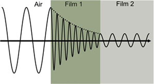
Figure 4: Light wave traveling from air into absorbing Film 1 and then transparent Film 2. Phase velocity and wavelength change in both materials depending on the refractive index (Film 1: n=4, Film 2: n=2).
Wavelength determines the optical constants. Figure 5 shows optical constants for TiO2 from UV to IR. Because of different processes that draw energy from the light wave, absorption (k>0) occurs in both UV and IR. IR absorption is usually caused by molecular or phonon vibration or free-carriers. UV absorption generally takes place because of electronic transitions, where light energy excites electrons to elevated states. Figure 5 shows that hypothetical or real optical constants are not independent, but mathematically linked through Kramers-Kronig relations.
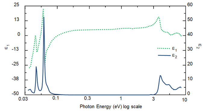
Figure 5: Complex dielectric function for TiO2 film with wavelengths from IR (small eV) to UV (high eV).
Light and materials interaction
Whenever light interacts with a material this leads to boundary conditions at the interface. During this, Maxwell’s equations must always stay satisfied. The below figure shows how incident light reflects and refracts at the interface. The angle between the incident ray and sample normal (θi) will be equal to the reflected angle (θr). Light that enters a material is refracted at an angle θt given by:
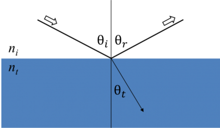
Figure 6: Light reflects and refracts according to Snell’s law.
At every interface a portion of light is reflected while the rest transmits at the refracted angle. Depending on the boundary conditions, different solutions apply for electric fields parallel and perpendicular to the sample surface. Light may thus be separated into orthogonal components with relation to the plane of incidence (p- and s-polarized). Both components can be calculated separately. This is how Fresnel described the amount of light reflected and transmitted at an interface between materials:


Multiple interfaces with proper Fresnel reflection and transmission coefficients occur with thin film and multilayer structures. To correctly define the reflected or transmitted beam, the relative phase of each light component must be tracked. The film phase thickness is thus determined as follows:

When several light waves superpose, interference occurs that depends on the relative phase of each individual light wave. The below figure shows the combination of light waves in the reflected beam and their corresponding Fresnel calculations.
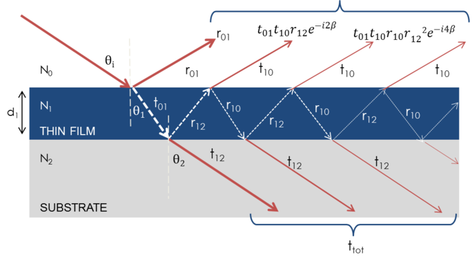
Figure 7: Light reflects and refracts at each individual interface, which leads to multiple beams in a thin film. Beam interference depends on the relative phase and amplitude of the electric fields. Beam reaction can be calculated with Fresnel reflection and transmission coefficients.
Measurements
Ellipsometry mainly measures how p- and s-components react in relation to each other during reflection or transmission. So a reference beam is always part of the experiment. A known polarization is reflected or transmitted from the sample and the output polarization is measured. The polarization change is the ellipsometry measurement:
![]()
Figure 6 shows a typical sample ellipsometry measurement. The linear incident light has both p- and s- components. The reflected light shows both amplitude and phase changes for both p- and s- polarized light. These changes are measured by ellipsometry.
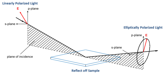
To collect ellipsometry data the following is needed: light source, polarization generator, sample, polarization analyzer, and detector. Both polarization generator and analyzer are made of optical parts which manipulate polarization: compensators, polarizers, and phase modulators. Typical ellipsometer configurations incorporate rotating analyzer (RAE), rotating polarizer (RPE), rotating compensator (RCE), and phase modulation (PME). The figure below shows an RAE configuration.

Unpolarized light is produced by a light source and then sent through a polarizer. The polarizer is set to allow only light with a certain electric field orientation to pass. Since the axis of the polarizer is aligned between the p- and s- planes, both reach the sample surface. The now linearly polarized light is reflected from the sample surface thus becoming elliptically polarized, and then sent through a continuously rotating polarizer (the “analyzer”). The amount of light that is allowed to travel through depends on the polarizer’s orientation in relation to the electric field ellipse of the sample. To define the reflected polarization, the light is converted to an electronic signal in the detector. Comparing this data to the established input polarization provides information on the change caused by the sample reflection: the ellipsometric measurement of Psi and Delta.
Data analysis
Ellipsometry is used to define material film thickness or optical constants by measuring the changes in light polarization. “Pseudo” optical constants from the ellipsometry measurement can be derived by reversing the data determined for a single reflection. This is useful for bulk material.

The above equation does not count with any surface layers. Nevertheless, there normally is a surface oxide or roughness in bulk materials. A direct inversion will include these data as part of the bulk optical constants. See fig. 10 for an overview of a typical data analysis process used in ellipsometry measurements. Since an exact equation cannot be written, a regression analysis is necessary. The answer is often overdetermined with only a few unknowns and hundreds of experimental data points. A regression analysis allows all of the measured data to be included when determining the solution.
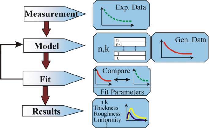
Figure 10: Flow chart for ellipsometry data analysis.
The following procedure is used for data analysis: the sample is measured and a model is made of the sample. With help of this model the assumed results from Fresnel’s equations, which describe thickness and optical constants of each material, are calculated. An appraisal of the preliminary calculation is made, if these values are unknown. The calculated values are compared to experimental data. To better match the experimental and calculation data, unknown material data can be varied. However, experimental data points should always be more than the unknown parameters. For example, maximally two material properties can be determined with a single-wavelength ellipsometer, as it produces exactly two data points: Ψ, Δ (Psi and Delta). Regression is used to find the best match between model and experiment. The difference between the data curves is quantified with help of an estimator like the Mean Squared Error (MSE). Unknown properties are varied until the minimum MSE is reached. This means that the lowest MSE is equivalent to the best answer.
View the figure below for the MSE curve versus film thickness for a transparent film on silicon. The lowest MSE value occurs at a thickness of 749 nm despite a number of local minima. Thus the correct film thickness is also 749 nm. The regression algorithm might consider a local minimum to be correct. So, to determine the correct global minimum it is wise to compare the results by eye for the lowest MSE.
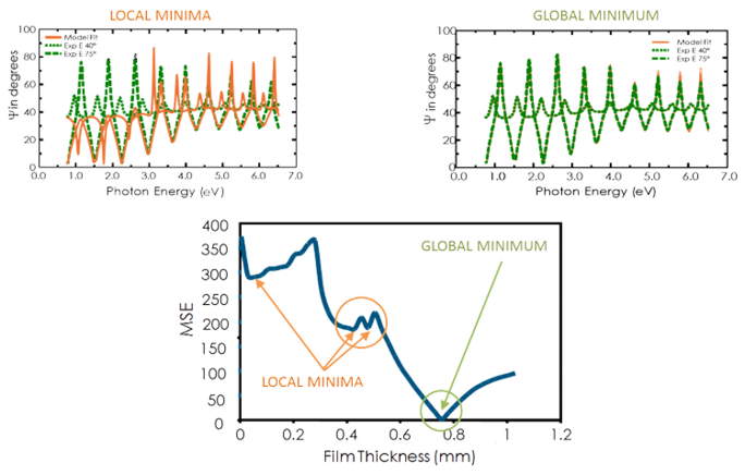
Figure 11, top-right: Experimental data and corresponding curves generated for the model at the global minimum. Figure 11, top-left: A similar curve at the local minimum near a thickness of 0.45 µm can easily be identified as incorrect result. Figure 11, bottom: The MSE curve versus thickness shows the global minimum. A regression algorithm can give local minima, but not the final result.
Determining film thickness
Film thickness is usually determined by the interference between light which reflects from the surface and the light that travels through the film. Whether this interference is considered constructive or destructive depends on the relative phase of the light which joins with the surface reflection. The interference includes both amplitude and phase information. The phase information from Δ is very sensitive to films down to sub-monolayer thickness. See the below figure for a comparison of reflected intensity and ellipsometry for the same series of thin SiO2 layers on Si. The reflectance for each film is nearly the same while there are large variations in Δ.

Figure 12, left: Reflected intensity and ellipsometric delta (right) for two thin oxides on silicon. The intensity measurement does not show that Delta is highly sensitive to films of nanometer scale.
Ellipsometry is commonly used for films from sub-nanometers to a few microns of thickness. With films thicker than several tens of microns, interference oscillations can only be resolved with increasing difficulty, except when longer infrared wavelengths are used. This is why for thicker films other measurement techniques are normally used.
To measure thickness, a portion of the light has to travel through the complete film and then return to the surface. With light-absorbing materials, optical thickness measurements can only be performed on thin and semi-opaque layers, unless they are performed on spectral regions with less absorption. For example, an organic film which absorbs UV and IR light may be transparent at mid-visible wavelengths. Metals strongly absorb at all wavelengths, so the maximum layer thickness which can be determined lays around 100 nm.
Optical Constants
Optical constants play an important role for thickness measurements. A film’s thickness influences the path length of the light that travels through the film, the index determines the light wave’s velocity and refracted angle. Both therefore contribute to the delay between light traveling through the film and the surface reflection. It is necessary to establish n and k as well as the thickness to obtain correct results from an optical measurement.
As a material’s optical constants vary for different wavelengths, all wavelengths that are analyzed with the ellipsometer must be individually determined. A material’s response at each wavelength can be anticipated by using a table of optical constants. To avoid the painstaking adjustment of unknown optical constants wavelength-by-wavelength it is favorable to use all wavelengths simultaneously. The adjustable parameters of a dispersion relation for example allow the overall optical constant shape to match the experimental results. Compared to adjusting individual n and k values for every wavelength, the number of unknown free parameters is reduced considerably.
Cauchy or Sellmeier relationships are frequently used to describe the index for transparent materials where the Cauchy relationship is normally given as:

with the three terms fitted to match the refractive index for the material. The Cauchy relationship is not limited by Kramers-Kronig (KK) consistency and can lead to unphysical dispersion. The Sellmeier relation on the other hand imposes Kramers-Kronig (KK) consistency, which ensures that the optical dispersion keeps a realistic shape. The Sellmeier relation is typically written as:

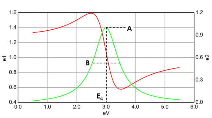
Absorbing materials often have a transparent wavelength region that can be modeled with the Cauchy or Sellmeier relation. While the absorbing region, however, must account for both real and imaginary optical constants. To describe the absorption for various materials, many dispersion relations utilize oscillator theory, including Lorentz, Harmonic, and Gauss. All of them share similar attributes with the absorption features being described with Amplitude, Broadening and Center Energy (related to frequency of light). The shape of the real component is calculated using Kramers-Kronig consistency after the imaginary behavior is described by the oscillator. To include possible extra absorption beyound the measured spectral region an offset to the real component is added. The Lorentz oscillator can be written as:
![]()
Figure 13 also shows Amplitude (A), Broadening (B), Center Energy (Ec) and offset (e1, off set) for a typical Lorentz oscillator. The energy E is related to the frequency of a wave, n:

The Planck’s constant h and the wavelength λ are given in nanometers. Other dispersion models, like Tauc-Lorentz and Cody-Lorentz, incorporate terms to describe the bandgap energy.
Further Reading
Ellipsometry is an established optical technique for the measurement of thin films and bulk materials. It uses the polarization changes caused by reflection/transmission from a material structure to determine the material’s characteristics like thickness and optical constants.
Aspnes D.E. (1985). The Accurate Determination of Optical Properties by Ellipsometry. In: Palik E.D. (ed.) Handbook of Optical Constants of Solids, pp. 89-112. Academic Press, Orlando.
Azzam R.M.A. and Bashara N.M. (1987). Ellipsometry and Polarized Light, Elsevier Science B.V., Amsterdam, The Netherlands.
Boccara A.C., Pickering C., and Rivory J. (eds.), (1993). Spectroscopic Ellipsometry, Elsevier Publishing, Amsterdam.
Collins R.W., Aspnes D.E., and Irene E.A. (eds.), (1998). “Proceedings from the Second International Conference on Spectroscopic ellipsometry”. In: Thin Solid Films, vols. 313-314.
Fujiwara H., Spectroscopic Ellipsometry, Principles and Applications, John Wiley & Sons, Ltd. 2007
Gottesfeld S., Kim Y.T., and Redondo A. (1995). “Recent applications of ellipsometry and spectroellipsometry in electrochemical systems”, In: I. Rubinstein (ed.), Physical Electrochemistry: Principles, Methods, and Applications, Marcel Dekker, New York.
Herman, I.P. (1996). Optical Diagnostics for Thin Film Processing, pp 425-479. Academic Press, San Diego, California.
Johs B. et al (1999). “Overview of Variable Angle Spectroscopic Ellipsometry (VASE), Part II: Advanced Applications”. Optical Metrology, vol. CR72, pp 29-58. SPIE, Bellingham, Washington.
Johs B. et al (2001). “Recent Developments in Spectroscopic Ellipsometry for in situ Applications”. In: Duparré A, Singh B (ed.) Optical Metrology Roadmap for the Semiconductor, Optical, and Data Storage Industries II, vol. 4449, pp 41-57. SPIE, Bellingham, Washington.
Roseler A. (1990). Infrared Spectroscopic Ellipsometry, Akademie-Verlag, Berlin.
Rossow U. and Richter W. (1996). “Spectroscopic Ellipsometry” in: Bauer G and Richter W (eds.) Optical Characterization of Epitaxial Semiconductor Layers, pp. 68-128, Springer-Verlag, Berlin.
Tompkins H.G. (1993). A User’s Guide to Ellipsometry, Academic Press, San Diego, California.
Tompkins H.G. and McGahan W.A. (1999). Spectroscopic Ellipsometry and Reflectometry, John Wiley & Sons, Inc., USA.
Tompkins, H.G. and Irene E.A. (eds.), 2005, Handbook of Ellipsometry, William Andrew Publishing, New York.
Tompkins, H. G. and Hilfiker, J. H., Spectroscopic Ellipsometry, Practical Application to Thin Film Characterization, 2016, Momentum Press Engineering
Woollam J.A. and Snyder P.G. (1992). “Variable Angle Spectroscopic Ellipsometry” in: Brundle CR, Evans CA, and Wilson S (eds) Encyclopedia of Materials Characterization: Surfaces, Interfaces, Thin Films, pp. 401-411, Butterworth-Heinemann, Boston.
Woollam J.A. et al (1999). “Overview of Variable Angle Spectroscopic Ellipsometry (VASE), Part I: Basic Theory and Typical Applications”. Optical Metrology, vol. CR72, pp 3-28. SPIE, Bellingham, Washington.
Woollam J.A. (2000). “Ellipsometry, Variable Angle Spectroscopic” in: Webster J.G. (ed.) Wiley Encyclopedia of Electrical and Electronics Engineering, pp. 109-116. John Wiley & Sons, New York.
Contact

Navigation
Categories
Contact
Quantum Design Turkiye
Sakarya Mah. Bassehir Sk. 14/A
06230 Altindag / Ankara
Turkey
| Phone: | +90 532 3205241 |
| E-mail: | turkeyqd-europe.com |


