AFM Dynamic Modes
Dynamic Force Mode
Dynamic force mode refers to a collection of AFM modes in which the cantilever oscillates at a high frequency at or close to resonance. A specific kind of dynamic mode, referred to as amplitude modulation mode (AM-AFM) is the most common AFM imaging mode. In AM-AFM, the amplitude of oscillation is the feedback parameter; other dynamic modes have different parameters for feedback such as frequency (frequency modulation) or phase (phase modulation). Amplitude modulation mode, tapping mode, intermittent contact mode, and dynamic force mode can be used synonymously.
As an imaging mode, dynamic mode offers several key advantages. Because the cantilever operates at resonance and interacts with the sample as the probe "taps" along the surface, it is a gentle interaction with the surface relative to static imaging modes that can preserve the sharpness of the tip. This kind of interaction also minimizes torsional forces between the probe and the sample, which are especially exacerbated in static imaging mode. These two advantages are particularly important for soft materials such as polymers or nanoparticles or fibrillar samples where dynamic modes are less destructive to the sample. Finally, by using the cantilever’s oscillation amplitude as the feedback parameter, the user is able to fine-tune the interaction between probe and sample between different regimes such as attractive and repulsive regimes.
In dynamic mode, the cantilever is generally driven with a shaker piezo and starts vibrating at the excitation frequency. By sweeping the frequency across a suitable range, the peak in the frequency spectrum that corresponds to the resonance frequency of the cantilever can be found. The cantilever is then driven with a sinusoidal motion at a fixed excitation energy, and it behaves as a damped spring or a single harmonic oscillator. As the oscillating cantilever is brought closer to the surface, the cantilever cannot oscillate at its full amplitude anymore and the amplitude of oscillation is reduced by the surface of the sample. This amplitude reduction is the source of the feedback; the user sets an amplitude based on the type of interaction that is desired.
The user should tweak 3 parameters during operation of dynamic mode:
- Cantilever spring constant: the stiffness of the lever must be appropriately suited to image the material. Often some empirical trial and error is required to find a suitable cantilever. If the cantilever is too stiff, the result may be destructive to the sample or cause tip wear. If the cantilever is too soft, it may not be able to interact with the sample to generate any contrast or it stays in contact with the surface.
- Free vibration amplitude: this is the amplitude of the oscillation by the cantilever when the cantilever is vibrating in free space away from the sample. This parameter is set in units of voltage. Rougher or sticky samples need a larger free vibration amplitude.
- Setpoint: this is the reduced target amplitude, which results after the tip is in intermittent contact with the sample. The setpoint is expressed as a percentage of the free vibration amplitude. Lower amplitude setpoints will favor a more aggressive tip-sample interaction or a more repulsive tip-sample interaction.
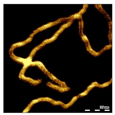
High-resolution topography image of double-stranded DNA (dsDNA) adsorbed to mica in buffer solution
Scan Size 110nm
Phase Imaging Mode
Phase contrast imaging is one of the most common AFM imaging methods to obtain contrast based on material properties. Phase contrast imaging is a form of dynamic mode and refers to the phase channel that is collected during this mode. An excited cantilever oscillation will exhibit a phase shift between the drive and the response.
When the interaction between an oscillating cantilever and a sample changes, the resonance frequency of the cantilever will shift: to lower frequencies for attractive forces, to higher frequencies for repulsive forces. Consequently, the phase at a fixed frequency shifts when the cantilever-sample interaction changes, for example when the material properties change; this is the reason that phase is a common imaging mode when contrast based on material properties is desired. However, the challenge with phase is that it will shift due to a convolution of multiple material properties, such as: adhesion, stiffness (modulus), dissipation, and viscoelasticity. Thus, while phase is a very useful imaging channel, it can be difficult to interpret the contrast with respect to individual material properties.
An additional challenge of phase imaging is a propensity towards imaging artifacts such as reversal of contrast or loss of contrast. These artifacts are primarily due to the problem of attractive-repulsive bistability where the tip-sample interaction toggles between net-repulsive and net-attractive regimes. This bistability can be controlled with a proper understanding of the cantilever physics and appropriate adjustment of operating parameters.
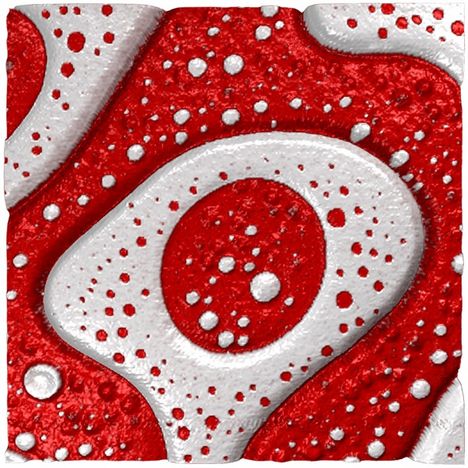
SBS-PS – Superposition of topography and phase
10µm x 10µm – Z range 18nm
Discover our AFM range here >>
| +39 06 5004204 | |
| +39 06 5010389 | |
| pergoliniqd-europe.com |