How does AFM work?

The AFM principle is based on a cantilever/tip assembly that interacts with the sample; this assembly is also commonly referred to as the probe. The AFM probe interacts with the substrate through a raster scanning motion. The up/down and side to side motion of the AFM tip as it scans along the surface is monitored through a laser beam reflected off the cantilever. This reflected laser beam is tracked by a position sensitive photo-detector (PSPD) that picks up the vertical and lateral motion of the probe. The deflection sensitivity of these detectors has to be calibrated in terms of how many nanometers of motion correspond to a unit of voltage measured on the detector.
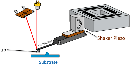
In order to achieve the AFM modes known as tapping modes, the probe is mounted into a holder with a shaker piezo. The shaker piezo provides the ability to oscillate the probe at a wide range of frequencies (typically 100 Hz to 2 MHz). Tapping modes of operation can be divided into resonant modes (where operation is at or near the resonance frequency of the cantilever) and off-resonance modes (where operation is at a frequency usually far below the cantilever’s resonance frequency).
The principle of how AFM works is depicted in the following schematic:
Another principle that is important to understand AFM operation is that of feedback. In atomic force microscopes, depending on the different modes, there is a parameter that serves as the setpoint, which is the parameter we want to keep constant during the scan. For example, in static mode (contact mode) the feedback parameter is the cantilever deflection, while in the most common form of tapping mode, the cantilever oscillation amplitude is the feedback parameter. The instrument is trying to keep this feedback parameter constant at its setpoint value by adjusting the z-piezo to move the cantilever probe up and down. The resulting z-piezo movements provide the height information to create the surface topography.
Control of the feedback loop is done through the proportional-integral-derivative control, often referred to as the PID gains. These different gains refer to differences in how the feedback loop adjusts to deviations from the setpoint value, the error signal. For AFM operation, the integral gain is most important and can have a most dramatic effect on the image quality. The proportional gain might provide slight improvement after optimization of the integral gain. The derivative gain is mainly for samples with tall edges. If gains are set too low, the PID loop will not be able to keep the setpoint accurately. If the gains are chosen too high the result will be electrical noise in the image from interference from the feedback.
The other parameters that are important in feedback are the scan rate and the setpoint. If the scan rate is too fast, the PID loop will not have sufficient time to adjust the feedback parameter to its setpoint value and the height calculated from the z piezo movement will deviate from the true topography at slopes and near edges. Very slow scan rates are typically not an issue for the PID loop, but result in long acquisition times that can pose their own challenges such as thermal drift. Optimization of the PID gains and the scan rate are necessary in order to optimize feedback loops. The setpoint affects the interaction force or pulses between probe and sample. A setpoint close to the parameter value out of contact feedback is most gentle for the sample, but tends to slow down the feedback.
| +39 06 5004204 | |
| +39 06 5010389 | |
| pergoliniqd-europe.com |